
In the discipline of hardware engineering, designing for high-frequency applications—such as 77GHz automotive radar, 5G base stations, or aerospace telemetry—requires a fundamental shift in mindset. At these frequencies, the printed circuit board is no longer just a passive carrier for components; it becomes an active part of the circuit itself. Over my years overseeing complex technical builds, I have seen brilliant schematic designs fail during physical testing simply because the engineer did not account for the mechanical realities of the factory floor.
To achieve pristine signal integrity, mastering Rogers PCB Manufacturing is essential. But engineers face a critical architectural decision early in the layout phase: should the design utilize a pure high-frequency stackup, or is a mixed-material approach more viable? This guide dives deep into the physics, the Design for Manufacturability (DFM) rules, and the structural mechanics of both configurations.
1. The Physics of Pure Pressing: When Compromise is Not an Option
A “pure” stackup means that every single dielectric layer and pre-preg bonding sheet within the board is composed of high-frequency materials, typically PTFE (Teflon) or ceramic-filled hydrocarbons. When your application demands ultra-low dielectric loss (Df) and absolute stability of the dielectric constant (Dk) across fluctuating temperatures, pure structures are the undisputed champions.
From an engineering standpoint, proper Rogers PCB Material Selection for a pure build eliminates internal reflections and phase shifts that occur when signals transition between layers of varying electrical properties. However, pure PTFE materials are mechanically soft. This softness presents severe challenges during fabrication, specifically regarding dimensional stability. Without the rigid backbone of fiberglass (FR4), pure Rogers boards are susceptible to stretching and warping during the extreme heat and pressure of the lamination cycle. Designing a pure board requires strict adherence to symmetrical copper balancing across all layers to prevent the final product from bowing like a potato chip.
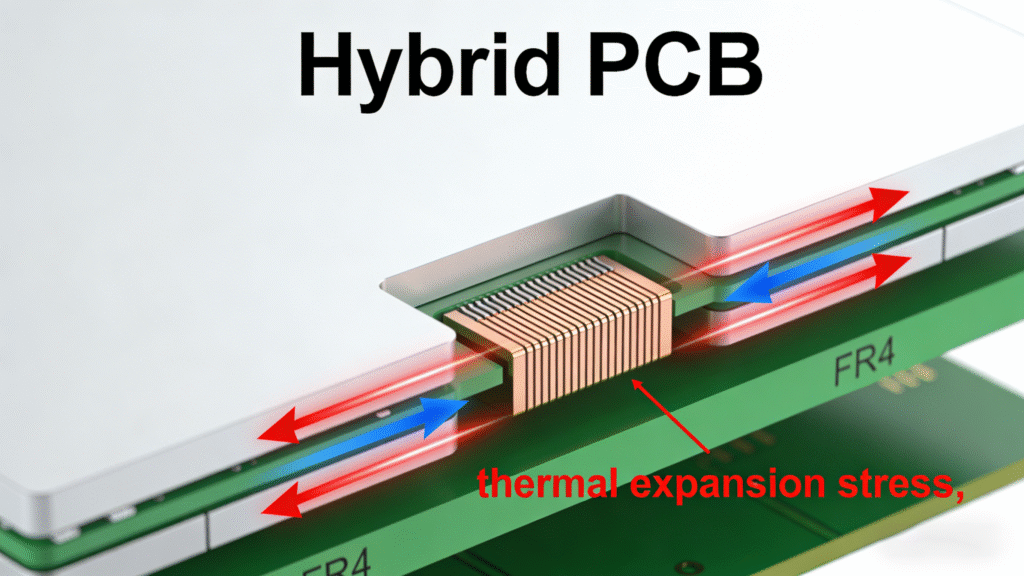
2. Engineering the Hybrid PCB Stackup: Mechanical Realities
Because pure high-frequency laminates are both expensive and mechanically challenging, engineers frequently employ the Hybrid PCB Stackup. In this architecture, the critical RF signals are routed exclusively on the outer layers utilizing Rogers laminates (e.g., RO4350B), while the internal layers—handling standard digital logic, power, and ground planes—are constructed using conventional FR4 epoxy glass.
This sounds like the perfect compromise, but it introduces a massive mechanical headache: the Coefficient of Thermal Expansion (CTE) mismatch. FR4 and Rogers materials expand and contract at vastly different rates when subjected to thermal stress. During the reflow soldering process, this unequal expansion generates immense shear forces within the Z-axis of the board. If the manufacturer does not apply specialized pressing profiles, these forces will literally tear the plated through-holes (PTH) apart, resulting in catastrophic open circuits.
3. Solving the Z-Axis Dilemma in RF PCB Fabrication
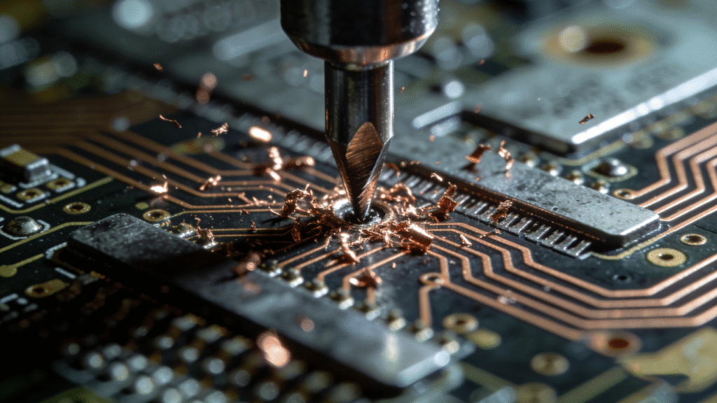
Successfully executing a hybrid design relies entirely on the factory’s capability to manage material transitions. In advanced RF PCB Fabrication, drilling through a hybrid board is a high-risk operation. The drill bit must pass through soft PTFE, hard ceramic fillers, and sticky FR4 resin in a single stroke.
Standard drilling parameters will cause the FR4 resin to smear across the inner copper layers, destroying the electrical connection. At Yichao, we combat this by utilizing internationally advanced DaZu six-axis drilling machines combined with highly specialized plasma desmearing processes. This ensures that the via walls are perfectly clean and ready for robust copper plating, regardless of the differing material densities.
4. Essential High-Frequency PCB Design Guidelines
To ensure your layout moves seamlessly from CAD to physical reality, engineers must follow strict High-Frequency PCB Design Guidelines when specifying mixed materials. Consider the following DFM rules:
- Symmetry is Mandatory: If you place a Rogers core on layer 1, you should ideally place a matching Rogers core on the bottom layer to balance the mechanical stress during lamination, even if the bottom layer doesn’t strictly require high-frequency performance.
- Resin Flow Control: Different pre-pregs melt and flow at different rates. Work with your manufacturer to select “no-flow” or “low-flow” pre-pregs near critical RF cavities or stepped grooves to prevent resin bleed onto your antennas.
- Impedance Trace Widths: Remember that the Dk of Rogers material drops slightly during the pressing process. Calculate your 50-ohm impedance traces based on the manufacturer’s specified *pressed* Dk, not just the raw datasheet value.
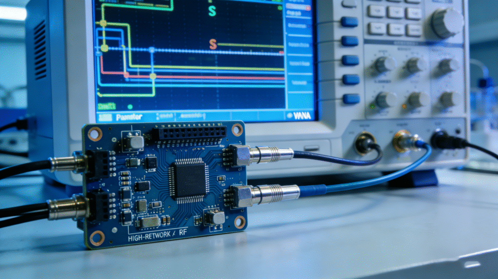
5. Validating Your RF Design with Yichao’s Smart Factory
The theoretical perfection of your RF design means nothing without flawless physical execution. Yichao Quick Technology has spent over a decade building a digital smart factory tailored for these exact engineering challenges. As a “specialized, refined, and innovative” enterprise, we support highly complex architectures, including boards up to 64 layers with HDI blind and buried embedding.
We do not guess when it comes to signal integrity. Our facility—certified to ISO9001:2015, ISO13485, and IATF16949 standards—employs rigorous quality control protocols. By utilizing LDI exposure machines for hyper-accurate trace definition and comprehensive AOI testing, we maintain a 99.8% product pass rate. When you are pushing the boundaries of physics with advanced RF designs, our 1-minute ordering and 12-hour fast shipping guarantee that your iterations happen faster, backed by manufacturing capability you can trust.
Conclusion
The choice between a pure and hybrid Rogers stackup is a delicate balance of electrical necessity and mechanical reality. By deeply understanding the CTE mismatches, resin behaviors, and drilling constraints inherent in these advanced materials, engineers can design robust boards that survive the factory floor. When combined with a sophisticated manufacturing partner like Yichao, your high-frequency innovations are built on a foundation of unyielding reliability.